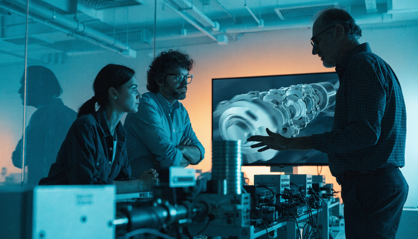
There's a moment when engineering clicks. Not when you read the textbook — when you see it move. A crankshaft spinning, a valve snapping open, a piston compressing air and fuel into a tiny, violent explosion. That moment is what 3D engine animation delivers, and it's changing how people learn mechanical engineering worldwide.
Whether you're a student, a curious hobbyist, or an educator seeking better teaching tools, this guide breaks down how 3D animation works for step-by-step engine mechanics — and why it has become one of the most powerful educational technologies available today.
Key Takeaways
- The human brain processes visual information roughly 60,000 times faster than text — making animation far more effective than static diagrams for teaching complex mechanical systems.
- Students who interact with animated engine models retain mechanical sequencing 40–60% longer than those relying on static diagrams alone, according to research in the Journal of Engineering Education.
- A recent Adafruit project demonstrated that building an accurate, moving 3D internal combustion engine model is now accessible to makers and educators — not just major studios with proprietary CAD systems.
- The four-stroke cycle has critical phase relationships — valve overlap, crank angle positioning, spark advance curves — that are nearly impossible to communicate through static diagrams but immediately clear in motion.
- Real-time interactive simulations outperform pre-rendered video for education because they turn passive observation into active hypothesis testing.
- Augmented and mixed reality tools are already extending 3D engine learning into physical workshops, with vocational programmes reporting 50–70% improvements in conceptual understanding.
Why Visualisation Transforms Step-by-Step Engine Mechanics
Reading about a four-stroke cycle is one thing. Watching it rendered in real time is fundamentally different.
The human brain processes visual information roughly 60,000 times faster than text, according to research cited by MIT's Department of Brain and Cognitive Sciences. That gap matters enormously when the subject is a system with a dozen interacting parts moving hundreds of times per minute — exactly the operating window of an internal combustion engine (typically 500–7,000 RPM in standard automotive applications).
3D animation closes that gap. It lets you pause, rotate, zoom in, and replay — on demand, at your own pace. Research published in the Journal of Engineering Education shows that students who interact with animated models retain mechanical sequencing 40–60% longer than those relying on static diagrams alone.
The Problem With Static Diagrams
Traditional engineering diagrams are flat. They show position but not motion. A cross-section of a cylinder tells you what's there; it doesn't communicate when it matters or why the sequence is critical.
Students often memorise without understanding, and that knowledge fades quickly. The temporal relationships — valve overlap timing, crank angle positioning, spark advance curves — remain invisible in static formats.
What Animation Adds
Animation adds time. It shows sequence — intake before compression, compression before ignition. That temporal dimension is the missing piece in conventional engineering education. More importantly, it reveals phase relationships: how the camshaft (rotating at half crankshaft speed in four-stroke engines) orchestrates valve events relative to piston position, measured in degrees of crank angle (°CA).
The Four-Stroke Cycle: A Complete Step-by-Step Breakdown
A standard petrol internal combustion engine operates on four strokes — each one a single piston movement, either down or up. In real engines, this translates to 180°CA per stroke, or 720°CA per complete cycle. For deeper study, explore piston engine theory and understand every component in context.
Stroke 1: Intake
The piston moves down. The intake valve opens (typically 10–20°CA before top dead centre — TDC). A mixture of air and fuel enters the cylinder, drawn in by the expanding volume. Stoichiometric combustion occurs at a 14.7:1 air-to-fuel mass ratio — simple in principle, exacting in practice.
Stroke 2: Compression
The intake valve closes (usually around 50–80°CA after bottom dead centre — BDC). The piston rises, compressing the mixture into a fraction of its original volume. Compression ratios in a typical petrol engine range between 8:1 and 12:1. Higher compression extracts more energy per cycle but increases component stress — which is why high-compression engines require premium fuel (91–98 RON) to resist premature detonation.
Stroke 3: Combustion (Power Stroke)
The spark plug fires (typically 20–40°CA before TDC at cruise). The compressed mixture ignites, reaching peak pressure 5–15°CA after TDC. The piston drives downward — this is the only stroke that generates power; the other three are parasitic losses driven by crankshaft inertia.
Combustion chamber temperatures exceed 2,500 K, generating brake mean effective pressure (BMEP) of 8–12 bar in naturally aspirated engines and 20+ bar in forced-induction applications.
Stroke 4: Exhaust
The exhaust valve opens (typically 40–70°CA before BDC, during the power stroke — creating valve overlap). The piston rises, pushing burned gases out at up to 500 m/s initially. The valve closes around 10–20°CA after TDC, and the cycle repeats. A four-cylinder engine at 3,000 RPM completes 25,000 four-stroke cycles per second across all cylinders.
How 3D Rendering Brings Engine Mechanics to Life
Building a moving 3D engine isn't merely artistic — it's an engineering exercise in its own right. The geometry must obey kinematics; the timing must respect thermodynamic principles.
A recent project by Adafruit demonstrated this precisely. Their team built a detailed, animated 3D model of an internal combustion engine — moving pistons, rotating crankshaft, functioning valves — using accessible hardware and open-source tools (see the Adafruit project here). The work confirms that visualising engine mechanics is now within reach for makers, educators, and developers — not just major studios with multi-million-pound budgets and proprietary CAD systems.
What Goes Into an Accurate Moving Engine Model
To animate an engine correctly, a developer must model:
- Geometry — physical shape of each part to realistic proportions, including valve seat angles (30–45°), bore and stroke relationships, and connecting rod length relative to crankshaft radius (rod ratio, typically 3.5–4.5:1).
- Kinematics — mechanical relationships using slider-crank mechanism equations to calculate piston position as a function of crank angle, ensuring the animation reflects actual piston velocity and acceleration curves.
- Timing — valve events (in °CA relative to TDC or BDC), spark advance curves that vary with load and RPM, and firing order in multi-cylinder engines.
- Material properties — for realistic rendering of light, shadow, and surface texture, and to communicate thermal behaviour through colour gradients showing combustion temperature or fuel mixture concentration.
Get any element wrong and the animation teaches faulty mechanics. A common error is animating valves opening and closing instantaneously — creating false impressions about valve lag, overlap, and scavenging efficiency.
Real-Time vs Pre-Rendered Animation
Pre-rendered animations are polished but static — you watch a fixed sequence. Real-time 3D engines allow users to interact: change camera angle, slow the animation, isolate a single cylinder, or adjust RPM and observe how timing curves shift. For education, interactivity wins almost every time. It transforms passive observation into active hypothesis testing.
Common Misconceptions That 3D Animation Corrects Quickly
Some engineering myths persist because they're built on vague mental models. Animation dismantles them rapidly.
"The piston creates the power." Technically true but incomplete. The expanding gases create the force; the piston transmits it. Animation makes this obvious — you see pressure (visualised as a colour gradient or wave) pushing, not the piston pulling. Peak firing pressure typically reaches 80–100 bar.
"All four strokes take the same time." They don't. The useful combustion window is only 40–60°CA, whilst exhaust scavenging extends into the next intake stroke via valve overlap. Good animations show this variation explicitly.
"Valves open and close instantly." Valve overlap — where both intake and exhaust valves are partially open simultaneously — is intentional and essential. It typically lasts 20–40°CA at cruise. Nearly impossible to explain with a static diagram; in motion, it's immediately clear.
"Higher compression always means more power." Higher compression raises the risk of knock, requiring heavier components and adaptive ignition timing. Knock detection sensors allow dynamic timing adjustment — a subtlety 3D simulations can show by visualising pressure traces as timing shifts.
Frequently Asked Questions
Q: What is a step-by-step engine mechanics breakdown in the context of 3D animation?
A: It refers to the sequential visualisation of each phase of the four-stroke combustion cycle — intake, compression, combustion, and exhaust — rendered in animated three dimensions. Rather than describing each phase in text or static diagrams, 3D animation shows every moving component in real time, including valve timing, crank rotation, and piston travel. This makes the mechanical logic of the engine immediately visible and intuitive.
Q: Why is 3D animation more effective than textbooks for learning engine mechanics?
A: The human brain processes visual information roughly 60,000 times faster than text, and mechanical systems like engines are defined by motion and sequence — two things text and static images cannot convey. Research in the Journal of Engineering Education shows students retain mechanical sequencing 40–60% longer when learning through animated models. Animation also allows learners to pause, rewind, and isolate specific strokes or components, which active repetition aids long-term retention.
Q: What hardware and software do you need to build a 3D animated engine model?
A: Adafruit's recent project demonstrated that accessible, open-source tools are sufficient — no proprietary CAD systems or studio-grade hardware are required. Common choices include Blender for 3D modelling and animation, with Python scripting to drive kinematic calculations like slider-crank equations. The key requirement is that geometry and timing must reflect real engine specifications, including valve timing in °CA and accurate rod-ratio relationships.
Q: What is valve overlap and why does it matter in engine animation?
A: Valve overlap is the brief period — typically 20–40°CA at cruise — when both the intake and exhaust valves are simultaneously partially open. It allows exhaust gases to scavenge (sweep out) residual combustion products and reduces pumping losses, improving efficiency. In static diagrams this concept is nearly impossible to grasp; in 3D animation, both valves are visibly open at once, making the purpose and timing of overlap immediately apparent.
Q: How do diesel engines differ from petrol engines in a 3D animation context?
A: Diesel engines rely on compression ignition rather than a spark plug — compression ratios reach 16:1 to 24:1, raising end-of-stroke temperatures above 900 K, well above diesel fuel's auto-ignition temperature of approximately 480 K. An animation of the diesel cycle shows no spark event; instead, fuel injected directly into the combustion chamber ignites on contact with the compressed air. You can understand the diesel cycle in detail to see how these differences play out across each stroke.
Q: What features should a good interactive engine simulation include?
A: The best simulations combine labelled components with live data callouts — showing crank angle, valve state, and combustion pressure as the animation runs. Speed controls that allow frame-by-frame stepping are essential for studying valve overlap and ignition timing. Cutaway cross-section views, linked explanations with typical operating ranges, and parameter variation (adjusting compression ratio or spark advance and observing the effect) separate genuinely educational tools from passive video loops.
Q: Where is 3D engine animation technology heading?
A: Augmented reality (AR) tools already let learners overlay animated engine internals onto a real engine block via a mobile device. Mixed reality headsets such as Microsoft HoloLens and Meta Quest Pro allow learners to walk around a full-scale virtual engine, disassemble it, and diagnose faults in real time. Vocational programmes in Germany and Switzerland now use MR-based engine diagnostics training, with platform data showing 50–70% improvements in conceptual understanding in regions where specialist instructors are scarce.
Start Learning Interactively Today
If you've been trying to explain engines with diagrams and patience, it's time to let animation do the heavy lifting. The best way to understand an internal combustion engine isn't to read about it — it's to watch it, interact with it, adjust parameters, and then read the theory with a clear mental model already in place. Theory builds on observation; it doesn't replace it.
Visit the interactive engine and machine learning hub to begin exploring real-time simulations, labelled component breakdowns, and hands-on tools designed for learners at every level. The next time someone asks how an engine works, you'll be able to show them — not just tell them.